Trouble Shooting
- Detailed Search
-
Search by Product
Search by Phenomenon
Search by Keyword
- Fluid leaks from the gland.
-
Check the packing retaining nut, gland bolts and nuts for looseness.
It is possible to prevent leakage by retightening them before use.● For valves with packing retaining nut design
Be sure to depressurize the inside of the valve and confirm that the pressure has dropped to the atmospheric level.
Retighten the nut with a spanner or wrench to the extent that the handle operation torque does not become to high.● For valves with gland nuts / bolts design
Be sure to depressurize the inside of the valve and confirm that the pressure has dropped to the atmospheric level.
Evenly tighten the gland nuts with a spanner or wrench so that the gland flange is installed parallel to the pipe.The gland area is sealed by the packing with pressure applied to its surface.
If the packing is kept under the surface pressure for a certain period of time, its shape is deformed with time.
As a result, stress relaxation takes place on the packing, and the nuts need to be retightened.
- The valve operation torque is abnormally high.
-
① If the packing retaining nut is tightened too tightly, the handle operation torque becomes too high.
Loosen the packing retaining nut while making sure that no leakage occurs.
Be sure to depressurize the inside of the valve before loosening the nut.② When the valve is installed to the pipe, apply an appropriate tool to the hexagonal piping connection port of the body located on the pipe side. The valve may be deformed when the valve body is clamped with a vice or pipe wrench for connecting to the pipe.
③ The pipe or fitting ends may hit the wall on the back of the body seat if they are excessively inserted to the valve bore. Such an installation may deform the body seat.
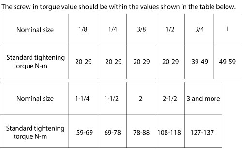
Copper materials are weaker in mechanical strength than steels, so if steel fittings are overly tightened into the bore of copper valve, this may deform the valve body.
When steel fittings are threaded into the copper valve bore, refer to the tightening torques shown in the table below before performing the work.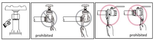
- Although the valve is fully closed, the seat still leaks.
-
① Foreign particles may be caught on the seat surface.
After the installation of the valve, the inside of the pipeline should be flushed with the valve fully opened to remove the foreign particles.② If the valve and the pipe are made of different metals, a cell may be formed because of the potential difference between the metals. This may cause galvanic corrosion inside the valve, leading to the possibility that the handle gets stuck or seat leakage occurs. Use the same material for the valve and the pipes when they are used in the same pipeline.
- The valve cannot be screwed into the piping.
-
① The pipe threads may be deformed.
The threads may be deformed when the valve is attached to the pipes with a pipe wrench or vice. Use an appropriate tool, such as a spanner, to retighten the valve with the proper tightening torque.
When installing the valve to the pipe, apply an appropriate tool to the pipe connection area of the valve body. Place the tool to the area near the side attached to the pipe.② Check that the pipe is not inserted obliquely.
Confirm that the pipe threads are machined in accordance with the thread standards that meet the product used..
- Fluid leaks from the screwed area.
-
When connecting the valve to the pipe, wrap PTFE seal around the male threads or apply a thin layer of suitable liquid sealant. Do not use a tool and screw the pipe manually to insert it to the deepest position of the valve bore, while carefully checking the feel for the right fit of the threads.
Choose and used an appropriate seal tape suitable to the fluid used, working temperature and other parameters. Make sure that the seal material does not enter inside the valve.
When wrapping the tape, it should be wrapped two or three times in the same direction as the thread-tightening direction.
If the tape is wrapped in the opposite direction, the pipe may be loosened during installation, leading to leakage.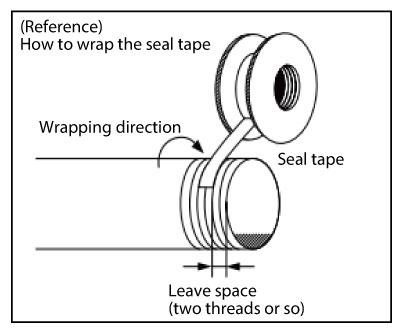
- The valve body was cracked, causing external leakage.
-
When the residual water in the pipe or valve is frozen, the product may be damaged and external leakage may occur.
In an environment where freezing is expected, remove the residual water from the pipe or implement the appropriate anti-freezing measures, such as thermal insulation or heater, to the valve and pipeline.
- The handle of the gate valve is too tight to operate.
-
The disc of the gate valve has a wedge-shape. So the more tightly the valve is closed, the more deeply the disc is wedged in, resulting in the disc getting stuck and the valve becomes inoperable.
When an operation assisting device is used, be careful not to apply excessive force.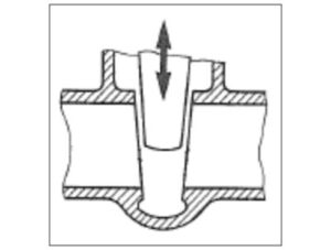
- Abnormal noise (chattering phenomenon) occurs.
-
If the flow is not constant, varies in speed or generates turbulence, pulsation, etc., the disc may come into contact with the valve disc, body or seat surface, causing abnormal noise (chattering).
Contact us for appropriate flow rate conditions.
- Leakage occurs from the connection area between the butterfly valve and flanges.
-
① When the valve is pushed in a narrow space between the pipe flanges, the rubber seat may be deformed, leading to leakage.
When installing the valve to the pipe, use jack bolts as needed to adjust the space between the pipe flanges.At this time, allow 6 to 10 mm extra space between the pipe flanges compared to the space between the valve surfaces and then insert the valve.Do not tighten the bolts at this time. Gradually tighten the bolts evenly and alternately in a star pattern to avoid uneven tightening. Tighten the bolts until both flanges come into contact with the valve body.
* If the bolts are further tightened even after the flanges come into contact with the valve body, the valve body may be damaged.
* Do not use an impact wrench to tighten the bolts.
Refer to our operation manual for more details on valve installation.② The pipe on the upstream and the one on the downstream may not be properly aligned. When installing the valve, be sure to align the center of the valve with that of the pipes. In doing so, be careful that excessive piping stress is not applied to the valve.
③ If the bolts are tightened unevenly, external leakage may occur.
Do not tighten the bolts at a time to avoid uneven tightening. Tighten the bolts evenly and alternately in a star pattern.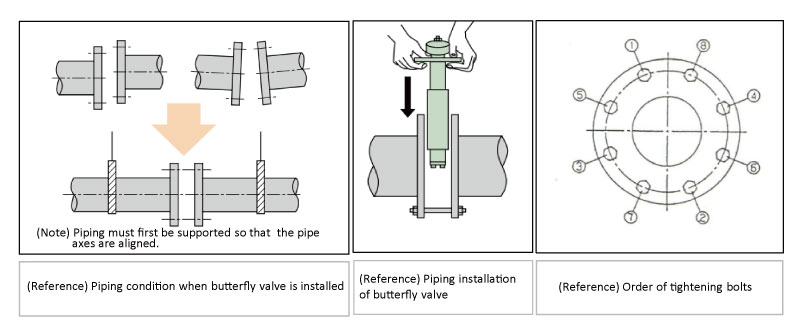
- The valve body of the butterfly valve was cracked.
-
① When the butterfly valve is pushed in a narrow space between the pipe flanges, the valve body may be cracked.
When installing the valve, use jack bolts as needed to adjust the space between the pipe flanges.
At this time, allow 6 to 10 mm extra space between the pipe flanges compared to the space between the valve surfaces and then insert the valve.② When the butterfly valve is installed without the proper alignment of the upstream pipe with the downstream pipe, the valve may be exposed to excessive stress, leading to cracking of the valve body. When installing the valve, be sure to align the center of the valve with that of the pipes.
③ If the bolts are tightened unevenly, excessive stress may be locally applied, leading to cracking of the valve body.
Do not tighten the bolts at a time to avoid uneven tightening. Tighten the bolts evenly and alternately in a star pattern.Refer to our operation manual for more details on valve installation.
- When I tried to install the valve, oil came out.
-
For our standard products, oil and grease are applied for the purposes of lubrication and rust prevention.
Contact us in case oil-free products are required.
- When an operation assisting device was used to open valve, the handle was rotated but the valve was not opened.
-
Because of the application of excessive force, the stem might be buckled or broken.
If an operation assisting device or the like has to be used for certain reasons, be careful not to apply excessive operating force.
- The actuator does not start even when power is turned on. (EA Series Actuator)
-
① Check that power is supplied the actuator.
② Check that the electric wires of the actuator are correctly connected to the terminal block and connectors.
③ Check that the connecting part of the crimp terminals is not blocked by the insulation cover of electric wires.
④ Check that the electrical continuity using an electric tester to detect any wiring disconnection.
⑤ Check that the power supply voltage and electrical current value are within the specification range of the actuator.
⑥ If the temperature inside the actuator excess 50°C, the internal components may get damaged or show abnormal operation.
When exposed to direct sunlight, provide a simple sunshade for protection.
- The actuator does not start even when power is turned on. (EX Series Actuator)
-
Check the manual handle to see if it is not in the pulled-up position.
When the handle is in the pulled-up position, a red belt mark can be seen.
If the handle is in the pulled-up position, push it down until it clicks (or the red mark is hidden).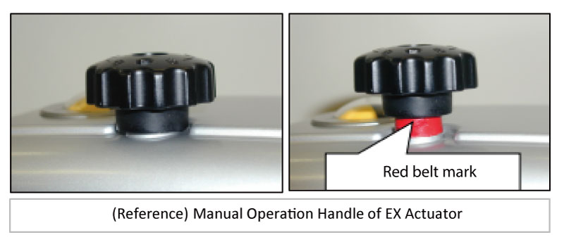
- The valve can stick in the fully opened (or fully closed) position. In addition, the actuator generates heat. (EX Series Actuator)
-
① Power may be supplied from both the valve opening and closing circuits to the actuator simultaneously.
Use an electrical tester and confirm that the two opposite electric circuits are not energized at the same time.② Check whether the opening and closing operations of the valve are not frequent.
If the opening and closing operations are frequent, set the duty factor to 30% or less.
As a guideline, ensure downtime of about 2.5 times or more of the opening and closing time.
- The opening and closing operations of the valve are repeated. (EX Series Actuator)
-
When the actuator is simultaneously driven in parallel with several other actuators, relays, and pumps with a single toggle switch, the currents between the devices may interfere with each other, causing the valve to repeatedly open and close without turning off the power, or causing the relay to chatter.
Use a relay with multiple contacts and use separate contacts for each device.
- When switched form the EK, EL Series Actuators to the EX Series Actuators, the actuators do not operate at all. (EX Series Actuator)
-
As opposed to the EK, EL Series Actuators (conventional models) where voltage contacts are used, the EX Series Actuators use no-voltage contacts. Therefore, independent power sources are required to the contacts for actuator operation and position signals separately.
The rated electric current values (the values of the electric currents that flow during operation) are different between the EK, EL Series and EX Series.
In case the EX Series is used in existing facilities where EK, EL Series was used, the electric current may exceed the allowable electric current of the components, such as relays, causing the components to melt and stick to each other due to electric energy during operation, and signal switching may not be possible.
- The valve does not operate. (C Series, B Series Pneumatic Actuators)
-
The supply pressure to the actuator may not be achieved.
Check the source of supply pressure, such as an air compressor, to see if it is working normally or if its capacity is sufficient.
Also, check the piping between the source of supply pressure and the actuator to see if it is not clogged, damaged, or frozen.
- The operation of the BS/BSW actuator is slow.
-
The air supply port of the actuator is clogged.
Or, air in the cylinder may not be exhausted sufficiently because the cap of the intake and exhaust port is still attached.
If the cap is still attached, air may be leaked from the actuator body. Therefore, be sure to remove the cap of the intake and exhaust port before operation.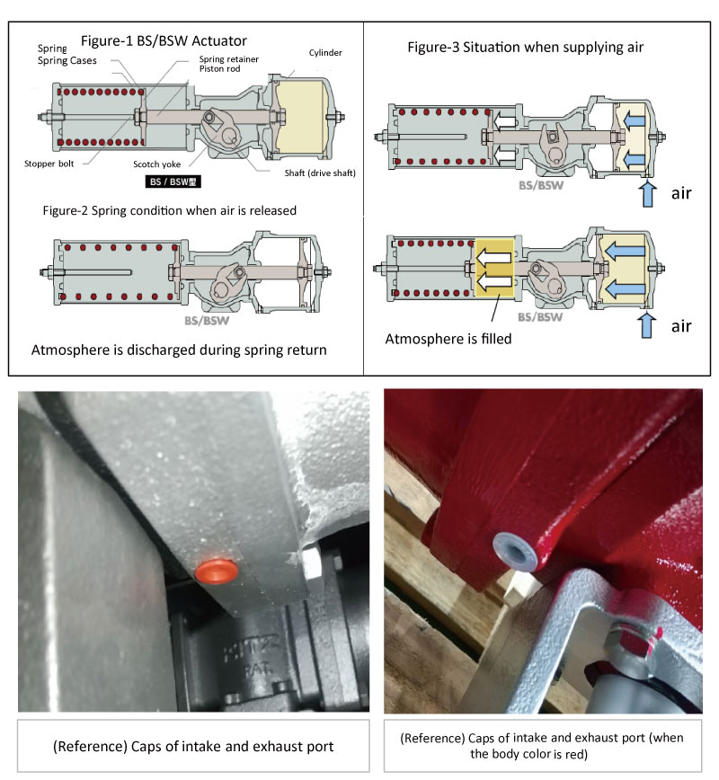
- There is a leak from the area of connection between the main pipe and T-Plus.
-
① The tightening torque for the pipe mounting bolts of the T-Plus may be insufficient, or the bolts may be tightened unevenly.
When the bolt tightening torque is insufficient or the bolts are tightened unevenly, the T-Plus and the pipe may be misaligned due to the impact caused by the piston movement, resulting in damage of the gasket because it is pulled by the pipe. This may cause external leakage in some cases.② The fluid may remain in the branch pipe.
Water used during the pressure test may remain in the pipe after the installation of the branch pipe. When the piston moves with that state, such movement may compress the water in the branch pipe, resulting in abnormal rise in pressure inside the branch pipe.
Because of the balance between this raised pressure in the branch pipe and the piston driving pressure causes insufficient lowering of the piston. The abnormally raised pressure from the branch pipe may damage the gasket, which is made of a piping material with a weaker strength, resulting in a condition prone to external leakage in some cases.③ The pipe may be deformed.
If the bolts for mounting the T-Plus to the pipe are tightened excessively, this may deform the pipe, the sealing performance of the gasket cannot be achieved, leading to external leakage. When tightening the bolts, refer to the tightening torque value shown below before performing the work.
Contact us
For inquiries about product technology, product purchases,
catalogs, and quality